 Nia Schlegel
This month, I had the honor of fucking up the entirety of the control of my Hermle.
Alarm 101: PLEASE CLEAR MEMORY
Everything started when this alarm appeared on the control. I had never seen it before, so of course my first reflex was to google it. That quickly led me to believe it was a non-critical error and I would just have to delete my programs. That didn’t matter much: the control has so little memory by modern standards (120 m of tape 48 kB) that I only ever kept the program(s) for the current job on it anyway. Everything else I read in over RS232.
And if anything went wrong, I had a full backup of the parameters (so I thought.)
Resetting Memory
So, looking through some forum posts and the official FANUC Maintenance Manual, I quickly found out the RAM could be cleared by pressing various combinations of keys during startup. The official manual says POWER ON + DELETE. That did nothing, so I thought I had misread it. In the back of my mind I had POWER ON + RESET + DELETE, which I had also read somewhere. I tried that and …
FUCK.
I had deleted the entirety of the RAM instead of just the programs. Even then I wasn’t panicking completely. I had a backup, after all. So I went to work: I opened the parameters page (there were no other pages left anyway), connected my laptop with the backup loaded and pressed INPUT, like I usually do to import stuff over serial.
Nothing worked. The manual didn’t help, so I asked the clanker, and it came up with a key combination: EOB + INPUT, which allows serial input in modes other than EDIT. I tried it for half an hour in different configurations and watched the bytes going over the serial line in all sorts of applications. Nothing happened. Not even the things I knew from my first months with the machine: the 086 not-ready alarm, or the blinking LSK/INPUT that should appear during communication.
I gave up and sent pleas for help to the Zerspanungsbude Forum, Fanuc and Hermle Support. It was the weekend so I had no option but to wait. In the meantime, the people on the forum pointed out that I would also need the DIAGNOSIS parameters, which I didn’t have a backup of. FUUUCK.
Right after the wipe, every axis showed a DGTL PARAM alarm on top of the usual ones, which means the servo parameters were gone:
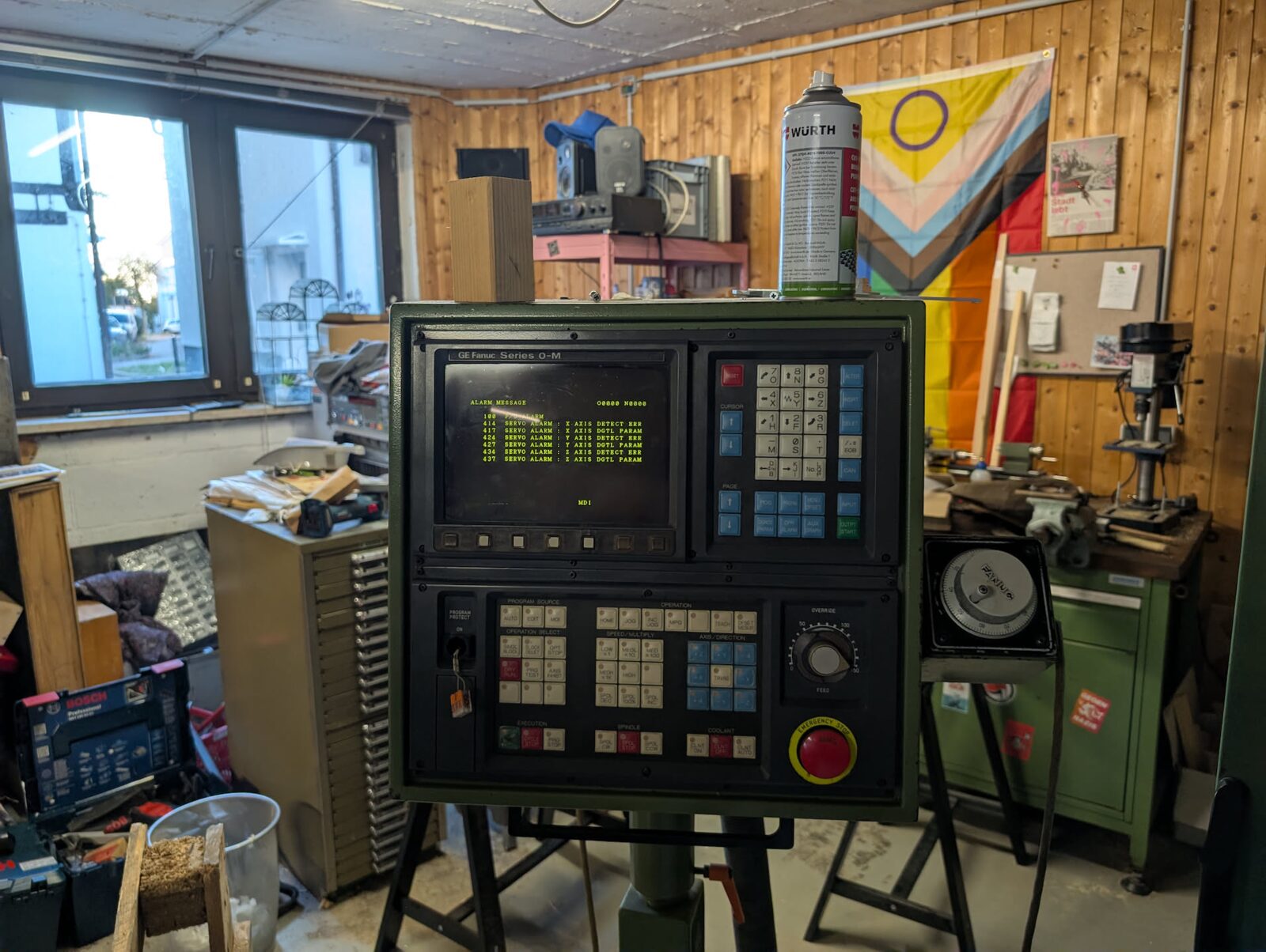
With nothing else to do while RS232 didn’t work, I started keying in thousands of parameters by hand. It only helped a little: the “missing parameter” alarms for the servos went away, but the machine was still in NOT READY state and nothing you would want to do on a mill worked.
Helpful Support??
The first people who answered were FANUC support. They were very helpful and surprisingly understanding of me running a 40 year old machine in production. The service tech on the phone told me about parameter 901: one of its bits tells the control that the serial interface exists at all. After the wipe it was off, so that’s why the control ignored everything I sent.
From Hermle I had asked for pretty much everything I could think of: the PMC ladder and its parameters (keep relays, data table, timers, counters), a standard parameter list for my serial number, whether the ladder lives in ROM or RAM, and a service partner near Düsseldorf who still works on this generation of controls.
An hour later, even Hermle answered. First, just to tell me they couldn’t help me, then, half an hour later they surprisingly found the factory backup of all parameters for my exact machine. As someone who normally mostly deals with consumer customer support I was flabbergasted and very happy. They sent me three dumps (probably written on MS-DOS and saved on some server for the last 40 years): the parameters, a nearly identical copy of the parameters I did not see the use of AND the DIAGNOSIS parameters (300–499) for which I had already given up all hope.
Serial Troubles. Again.
With this new boost of motivation, I got straight to work. Parameter 901 is part of the 900 range, which holds the options the original customer bought. None of the backups (Hermle’s or mine) included them, but I found a PDF with a complete list. I set the bit in 901 that enables the serial interface, rebooted and finally arrived at an old friend of mine.
086 P/S ALARM
The DR signal alarm. Huh? I hadn’t changed anything about the hardware setup I had arrived at after lots of trial and error earlier in the year, and my transfer application was the same too. So it had to be one of the thousands of parameters I had just retyped, and I had no idea which one.
Annoying, but then I just had to do the hack I had found too annoying the first time: jumpering DR on the connector, so it’s set electrically instead of by the adapter. I jammed a few strands of stranded wire from a broken USB-C cable straight into the DE9 and DB25 connectors (both, to be safe :D) and went from the 086 alarm to … the 087 alarm. Now that DR was always high, the control never stopped reading. If I pressed Send on my laptop too slowly, the control timed out waiting, and sending afterwards led to the overflow alarm. So I just had to reboot every time something went wrong. Small price to pay.
Loading the full parameter backup
So I loaded the backup. Right after rebooting, more alarms went away and more of the UI looked like it used to. Apparently typing thousands of parameters by hand is not one of my natural talents. I had gotten further, but the machine was still unusable: the axes didn’t move, and AUTO and EDIT modes still didn’t work (as far as I could tell).
I also couldn’t open the PMC ladder screen anymore, so I was really worried the ladder was gone. That would probably have been the death sentence for the 0M control. Reflashing it without a backup, with a proprietary MS-DOS tool from the 80s, did not seem feasible.
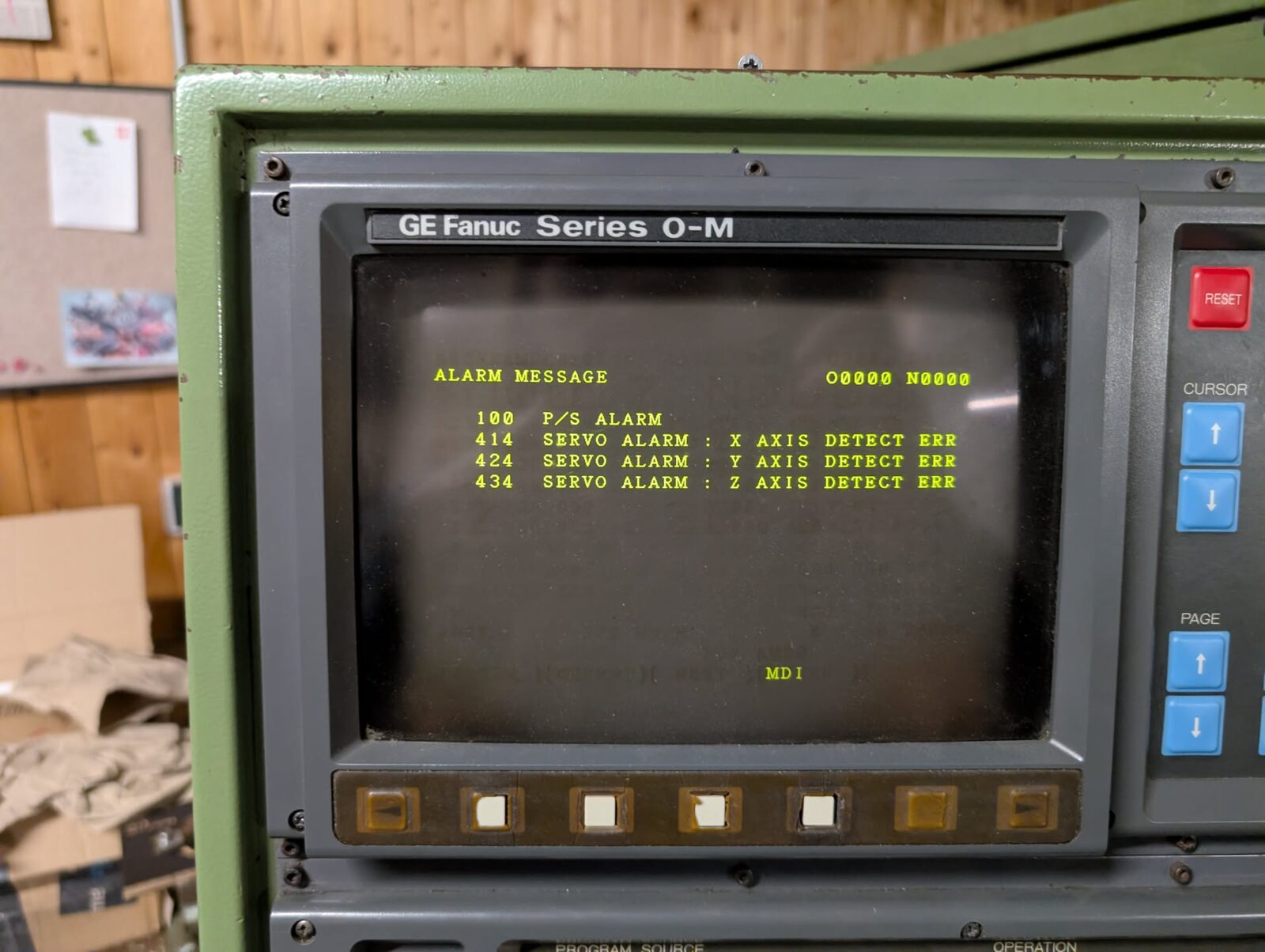
At least the alarm list got shorter. Only the DETECT ERR alarms for the three axes were left, plus alarm 100, which just means parameter writing is still enabled:
Enabling options
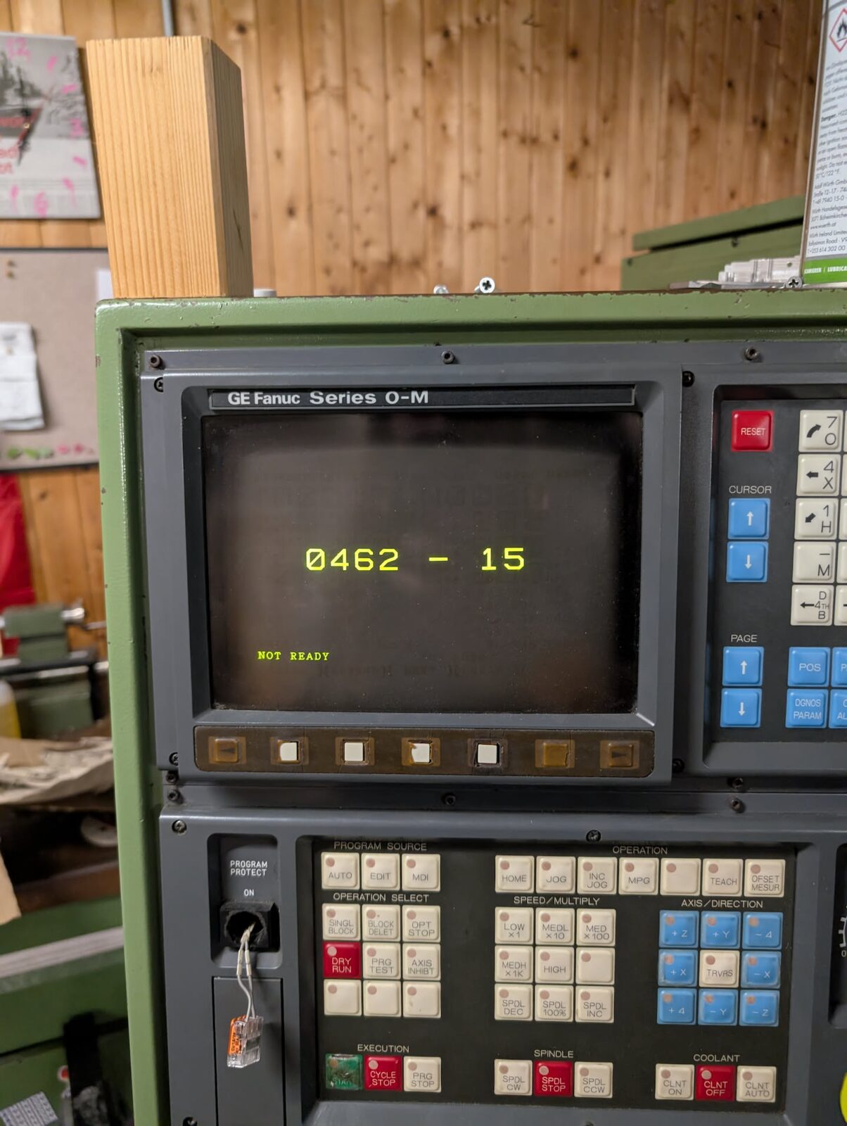
Most of the time, the control didn’t even get past its boot screen. All it showed was the software version and NOT READY:
The option parameters (900–923) tell the control which features the original customer paid for. Each one is a byte, and each bit is one option. Apart from the RS232 bit they were all still zero, and one of them turned out to be the reason nothing worked: parameter 905, which tells the control which PMC (the PLC running Hermle’s ladder logic) is installed.
| 905 bit | PMC |
|---|---|
| 0 | PMC-L |
| 1 | PMC-M 3000 steps |
| 2 | PMC-M 5000 steps |
| 3 | PMC-M 8000 steps |
| 4 | PMC-M 12000 steps |
With all bits cleared, the ladder (which luckily lives in ROM, not RAM) never runs. That explained everything: the emergency stop signal goes through the PMC, so no PMC means permanently NOT READY. The mode keys are read by the PMC too, so the control was stuck in MDI, and of course there was no PMC screen. I couldn’t find a PMC-M board in the cabinet, so it had to be the built-in PMC-L: 905 = 00000001. Reboot, and the PMC screen was back. And with it, I could finally home the machine again.
Then I went through the option list and set the bits for the features the machine had:
| Param | Value | Options |
|---|---|---|
| 900 | 00001011 |
canned cycles, G10 offset input, handwheel (MPG) |
| 901 | 11100010 |
120 m tape memory, chamfering/corner radius, reader/puncher interface (RS232), multiple repetitive canned cycles |
| 903 | 10110100 |
actual spindle speed output, MDI B, 125 programs, soft keys below the CRT |
| 905 | 00000001 |
PMC-L |
| 906 | 00010000 |
99 offsets |
| 907 | 01010000 |
run hour/parts count display, cutter compensation C (G41/G42) |
| 909 | 10000000 |
simple tool life management |
| 910 | 11011111 |
program restart, work offsets (G54–G59), operator messages, helical interpolation, F1-digit feed, automatic corner override, thread cutting |
| 911 | 00101101 |
single direction positioning, rigid tapping, clock and counters, 400 offsets |
| 912 | 00110101 |
3rd/4th reference point return, G68 coordinate rotation, tool life management, 200 offsets |
| 913 | 10000010 |
polar coordinates (G15/G16), user macro B |
| 915 | 10000000 |
200 registerable programs |
| 916 | 10000000 |
graphic display B |
| 917 | 00010000 |
additional macro variables |
Bit 0 is the rightmost digit. You have to type all eight digits and press INPUT, and after every change the control throws 000 and wants a power cycle.
Making parts again
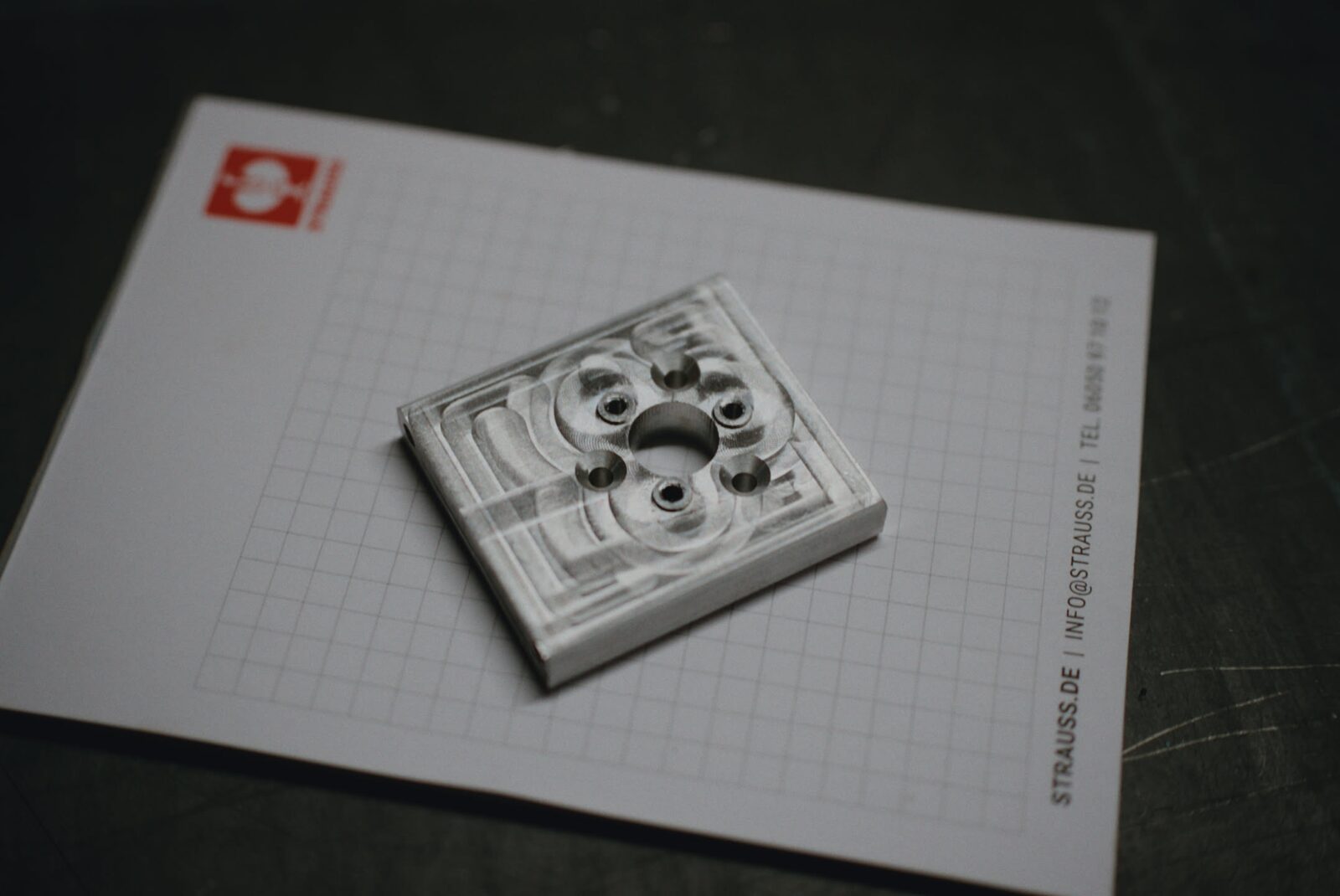
After all of that, the machine is back to making parts even better than before, because I now have the cycle time option. Lessons learned: read the manual twice before holding down keys at power-on, and back up everything, including the DIAGNOSIS and option parameters. Here’s a picture of the first part I made after it ran again, a bracket for the robocup team of my little brother.
Appendix: all option bits
Here is the full list of option bits for reference (✓ = enabled on my machine). I also made it into a PDF.
| Param | Bit | Option | |
|---|---|---|---|
| 900 | 0 | CANNED CYCLE | ✓ |
| 900 | 1 | G10 PROGRAM INPUT OF OFFSET | ✓ |
| 900 | 2 | MECHANICAL HANDLE FEED | |
| 900 | 3 | MANUAL ONE PULSE GENERATOR CONTROL | ✓ |
| 900 | 4 | S4/S5 DIGIT CONTROL | |
| 900 | 5 | INCH / METRIC CONVERSION | |
| 900 | 6 | SPECIAL G CODE | |
| 901 | 0 | TAPE MEMORY ADDITION 320M | |
| 901 | 1 | TAPE MEMORY ADDITION 120M | ✓ |
| 901 | 2 | TAPE MEMORY ADDITION 80M | |
| 901 | 3 | TAPE MEMORY ADDITION 40M | |
| 901 | 4 | TAPE MEMORY ADDITION 20M | |
| 901 | 5 | CHAMFERING, CORNER RADIUS | ✓ |
| 901 | 6 | READER/PUNCHER INTERFACE CONTROL | ✓ |
| 901 | 7 | MULTIPLE REPETITIVE CANNED CYCLE | ✓ |
| 902 | 0 | TWO MANUAL PULSE GENERATOR CONTROL | |
| 902 | 2 | CONSTANT SURFACE SPEED CONTROL | |
| 902 | 3 | SPINDLE SPEED FLUCTUATION DETECTION | |
| 902 | 4 | PATTERN DATA INPUT | |
| 902 | 5 | STORED PITCH ERROR COMPENSATION | |
| 902 | 6 | CUSTOM MACRO A | |
| 902 | 7 | PLAYBACK | |
| 903 | 0 | MIRROR IMAGE FOR DOUBLE TURRETS | |
| 903 | 1 | X AXIS MIRROR IMAGE | |
| 903 | 2 | ACTUAL SPINDLE SPEED OUTPUT | ✓ |
| 903 | 3 | DIRECT INPUT OF OFFSET B | |
| 903 | 4 | MDI EXEC. B | ✓ |
| 903 | 5 | NUMBER OF PROGRAMS 125 | ✓ |
| 903 | 6 | EXTERNAL KEY INPUT | |
| 903 | 7 | SOFT KEYS BELOW CRT | ✓ |
| 904 | 0 | JAPANESE | |
| 904 | 1 | GERMAN/FRENCH MESSAGE | |
| 904 | 2 | CHINESE | |
| 904 | 3 | ITALIAN | |
| 904 | 4 | SPANISH | |
| 904 | 5 | HANGEUL | |
| 905 | 0 | PMC MODEL L | ✓ |
| 905 | 1 | PMC MODEL M 3000 STEP | |
| 905 | 2 | PMC MODEL M 5000 STEP | |
| 905 | 3 | PMC MODEL M 8000 STEP | |
| 905 | 4 | PMC MODEL M 12000 STEP | |
| 906 | 0 | MENU PROGRAMMING | |
| 906 | 3 | ADDITIONAL OFFSET MEMORY 64 | |
| 906 | 4 | ADDITIONAL OFFSET MEMORY 99 | ✓ |
| 906 | 5 | TOOL LENGTH MEASUREMENT | |
| 906 | 7 | EXTERNAL TOOL COMPENSATION | |
| 907 | 1 | 2ND AUXILIARY FUNCTION B 8-DIGIT BINARY | |
| 907 | 2 | SIMULTANEOUS 3 AXIS CONTROL | |
| 907 | 3 | ADDITIONAL AXIS CONTROL | |
| 907 | 4 | HOUR RUN / PARTS COUNT DISPLAY | ✓ |
| 907 | 6 | CUTTER COMPENSATION C G41/G42 | ✓ |
| 907 | 7 | CUTTER COMPENSATION B | |
| 908 | 0 | HANDLE INTERRUPTION | |
| 908 | 3 | JOG OVERRIDE | |
| 908 | 5 | GENERAL PURPOSE SOFTWARE OPERATOR’S PANEL | |
| 908 | 7 | SOFTWARE OPERATOR’S PANEL | |
| 909 | 0 | GRAPHICS DISPLAY | |
| 909 | 1 | CONVERSATIONAL TYPE PROGRAMMING WITH FIGURE | |
| 909 | 3 | STROKE LIMIT EXTERNAL SETTING | |
| 909 | 6 | EXTERNAL MESSAGE | |
| 909 | 7 | SIMPLE TOOL LIFE MANAGE | ✓ |
| 910 | 0 | PGM RESTART | ✓ |
| 910 | 1 | WORK OFFSETS G54-G59 | ✓ |
| 910 | 2 | OPER. MESSAGE | ✓ |
| 910 | 3 | HELICAL INT. | ✓ |
| 910 | 4 | F1 DIGIT FEED | ✓ |
| 910 | 5 | AXIS CONTROL BY PMC | |
| 910 | 6 | AUTO. CORNER OVERRIDE | ✓ |
| 910 | 7 | THREAD CUTTING AND SYNCHRONOUS FEED | ✓ |
| 911 | 0 | SINGLE DIRECTION POSITIONING | ✓ |
| 911 | 2 | RIGID TAP | ✓ |
| 911 | 3 | CLOCK AND COUNTERS | ✓ |
| 911 | 4 | CHANGES XYZ TO @ | |
| 911 | 5 | 400 OFFSETS | ✓ |
| 911 | 6 | DIRECTION DISPLAY OF FLOPPY CASSETTE | |
| 911 | 7 | DECIMAL POINT DISPLAY | |
| 912 | 0 | 3RD / 4TH REFERENCE POINT RETURN | ✓ |
| 912 | 1 | G50, G51 SCALING | |
| 912 | 2 | G68 COOR-SYS-ROTATE | ✓ |
| 912 | 3 | F10/11 TAPE FORMAT | |
| 912 | 4 | TOOL LIFE MANAGEMENT | ✓ |
| 912 | 5 | 200 OFFSETS | ✓ |
| 912 | 6 | ADDITIONAL OPTIONAL BLOCK SKIP 9 | |
| 912 | 7 | MACRO EXECUTER OR AUX / GRAPH DISPLAY | |
| 913 | 1 | G15, G16 POLAR COORDINATE SYSTEM | ✓ |
| 913 | 4 | I/O DEVICE EXTERNAL CONTROL | |
| 913 | 5 | SIMULTANEOUS 4 AXIS CONTROL | |
| 913 | 7 | USER MACRO B | ✓ |
| 914 | 1 | REMOTE BUFFER STORAGE | |
| 914 | 2 | HIGH SPEED REMOTE BUFFER STORAGE A | |
| 914 | 3 | HIGH SPEED REMOTE BUFFER STORAGE B | |
| 914 | 4 | READER PUNCHER INTERFACE CONTROL 2 | |
| 915 | 5 | 5 AXIS CONTROL | |
| 915 | 7 | 200 REGISTERABLE PROGRAMS | ✓ |
| 916 | 0 | TOOL OFFSET G45-G48 | |
| 916 | 7 | GRAPHIC B | ✓ |
| 917 | 4 | ADDITIONAL MACRO VARIABLES 149-199, 531-999 | ✓ |
| 923 | 5 | 48 WORK OFFSETS |