Reversing a Cinema Camera’s Peripherals Port
2025-11-11 #rev, #embedded, #fs7, #electronics
Update 2025-12-28
I tried summarizing this blog post in a 5 minute lightning talk on 39C3. (being pretty nervous though haha)
Original
So recently (actually three months ago), I acquired a used Sony PXW-FS7. It’s very heavy but produces also produces very nice images, which is all I wanted of it.
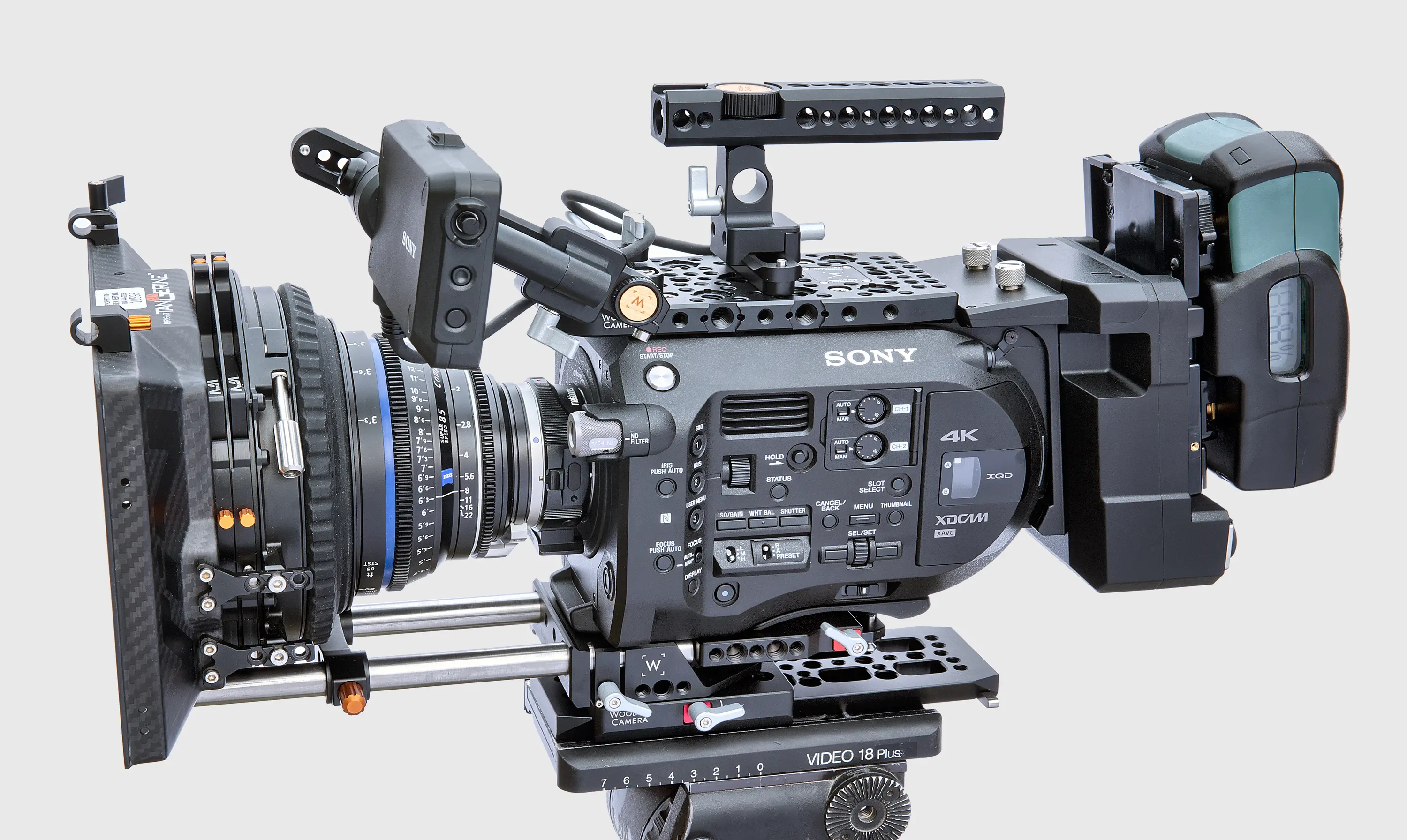
(This is what it looks like rigged-out, mine has less stuff. Pic from the internet)
It has this weird if you’re not used to ENG cameras side grip for holding the camera when it’s on your shoulder and then controlling it in a pretty ergonomic way. My only real problem with it that some buttons can only be reached using this removable accessory. Particularly the user buttons 4–6 (if you know old Sony menu systems you know the need for shortcut buttons.) This becomes evident when not shooting from the shoulder but e.g. the hip. You hold it from the top handle and can’t reach the buttons I use for focus zooming which is essential when using a camera that has zero usable auto focus (with a manual lens lol).
I thought a bit and came to the conclusion that since it’s a tool used in an industry that kind of expects expandability and modularity (to a degree, but think of RED’s business model for example) and that the camera is already over 10 years old it would not be an extraordinarily complex/secure protocol the camera uses to communicate with the electronics in the grip.
And so, without ever having attempted anything resembling this complexity and only knowing how an oscilloscope worked in theory, I made it my mission to reverse engineer the protocol and develop my own hardware to have another set of buttons on the top handle (or wherever to be honest.)
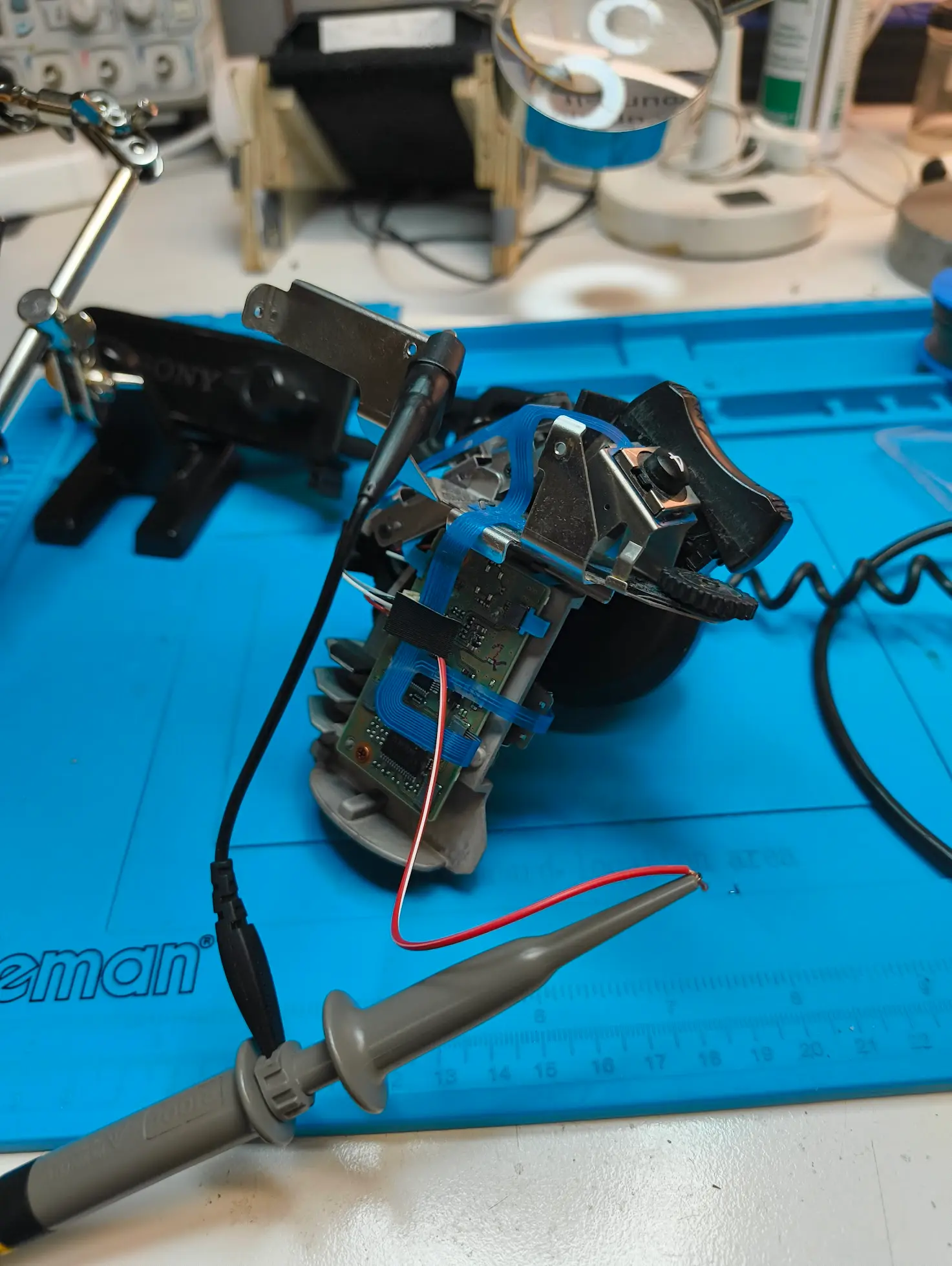
I had 23n27 who randomly was also at chaosdorf at that there holding my hand a little so we quickly figured out it was a serial protocol looking veeeery similar to UART at 9600 baud. Of course we only had one wire which was a bit weird to me at first but that just means it’s an open-drain bus. The camera wiggles the voltage for a “placeholder” of sorts for eight bytes of all zeroes and whenever it’s low, the grip can pull it high.
This is very visible when pushing one of the buttons on the grips. The third (and fouth?) byte is changed by the grip to reflect one of the unique ids each button and dial actuation has. This signal stays pretty permanent as long as the button is pressed. There can only ever be one action at a time.

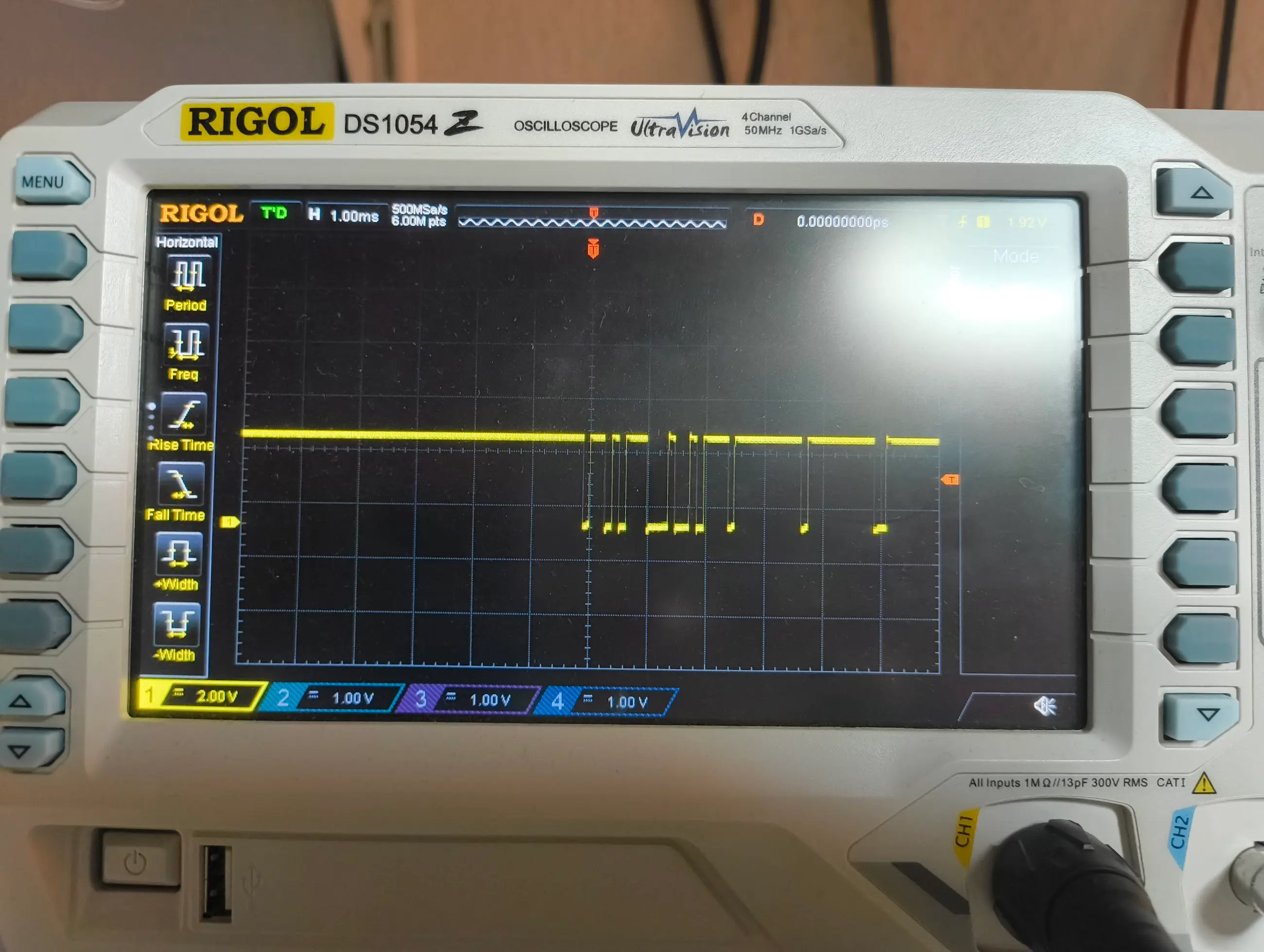
After the long and annoying process of getting the traces out of the oscilloscope and into sigrok/pulseview (I ordered a logic analyzer immediately after doing this once) and recording for a bit we can see the difference between pressing one of the buttons and the idle signal. There’s also a cyclic thing happening every couple of packets but that doesn’t seem to matter to the camera.
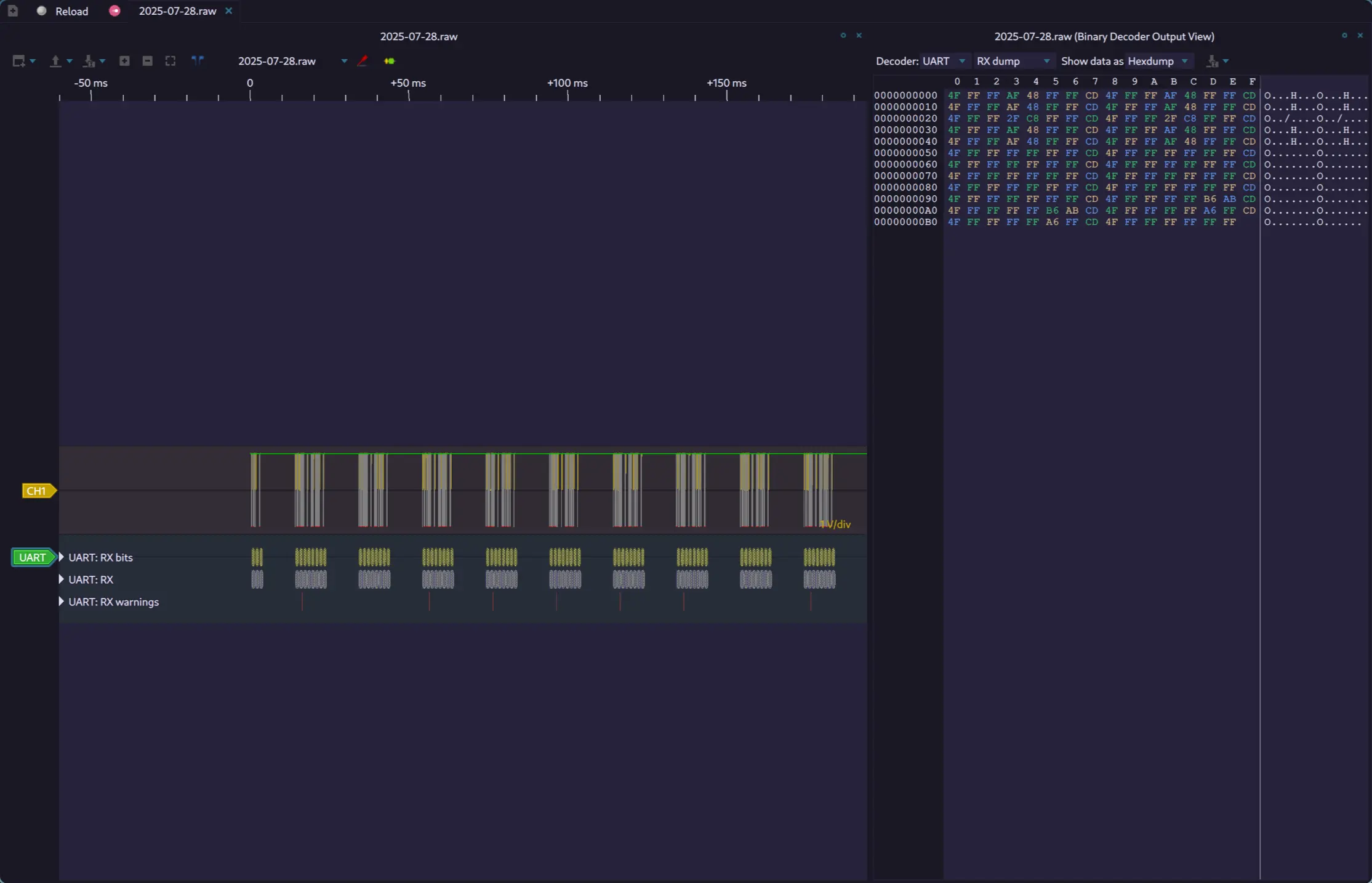
From this, we can also extract the first identifier for one of the buttons! The second byte is 0xd7 and the third 0x48!
First Simulator
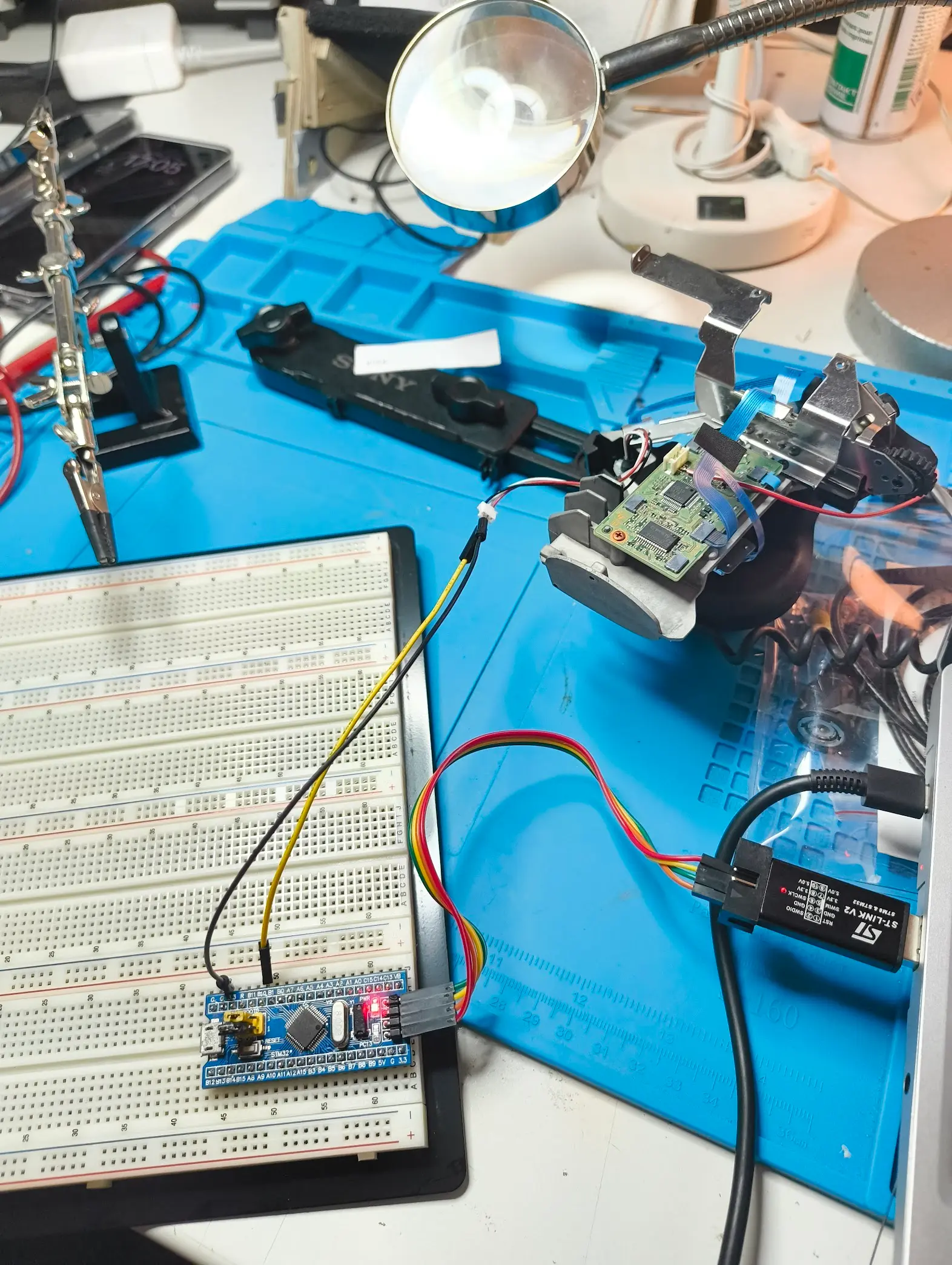
For my first prototype I used an STM32 F-Series board I had laying around. We only need two pins (which the STM32 is total overkill for): GND and a GPIO. The only thing really making this harder than just turning it on/off is that we need to both read the voltage and write it but this protocol is so slow you can literally just change the type on the fly lol—or as we are doing, just making it both an in- and output.
So we finally get to some code!
fn write_byte<P: InputPin + OutputPin>(io: &mut P, byte: u8, delay: &mut Delay) {
    let theoretical_delay_us = 104;
    let write_duration_us = 3;

    let delay_us = theoretical_delay_us - write_duration_us;

    for i in 0..8 {
        if (byte >> i) & 1 == 1 {
            io.set_high().ok();
        } else {
            io.set_low().ok();
        }
        delay.delay_us(delay_us);
    }
}

pub fn write_lanc<P: InputPin + OutputPin>(io: &mut P, cmd: &LancCmd, delay: &mut Delay) {
    let repeat_count = 5;

    for _ in 0..repeat_count {
        // wait for start bit
        loop {
            let last_low = embassy_time::Instant::now();
            while !io.is_low().unwrap() {
                nop();
            }
            let elapsed = last_low.elapsed();

            if elapsed.as_micros() > 5000 {
                // debug!("Start bit detected after {} us", elapsed.as_micros());
                break;
            }
        }
        delay.delay_us(104);

        write_byte(io, cmd.mode, delay);
        let _ = io.set_high();
        loop {
            let last_low = embassy_time::Instant::now();
            while !io.is_low().unwrap() {
                nop();
            }
            let elapsed = last_low.elapsed();

            if elapsed.as_micros() > 200 {
                break;
            }
        }
        delay.delay_us(104);
        write_byte(io, cmd.cmd, delay);
        let _ = io.set_high();
    }
}
Disclaimer: this is not strictly following best practices because I am not very good at rust, but thsi version works and still does after changing architecture completely to a WCH32V003. What we are basically doing is waiting for the start bit (each packet is spaced apart quite a bit) and then overwriting the second byte with the mode and the third with the command. The mode is always constant, the command depends on the button )
PCB
As the setup with the STM32 on a breadboard is not exactly run-and-gun I got started working on a PCB based on a WCH32V003 because it seemed wasteful to use a full-on stm32 with 30 GPIOs and tons of stuff I don’t need. Also the STM32F103C8T6 I used originally costs over $1 on LCSC while a pack of 50 WCHs cost less than $10.
I wanted it to fit on the top handle crossbar between the top-handle and monitor mount so I was pretty space-constrained. I was pretty sture I could fit a PCB measuring 25 mm across on it.
I came up with a design in an afternoon or two and got it shipped from china. After soldering it for the first time I noticed it powered on and took firmware, but only very rarely and none of the buttons worked. The footprint I used for the buttons was oriented wrong so I had to bodge in their ground connection from somewhere else.
It still powered off randomly and flashing/debugging only worked while pressing ranodm buttons on the PCB and only after trying 20 times. After many days debugging and looking at the datasheet and my Kicad project I noticed the FUCKING RESET AND GROUND PINS WERE FLOATING. So I also fixed that :3 and ported my STM32 rust code to this MCU which was surprisingly easy coming from C development since both have crates implementing the embedded_hal traits.
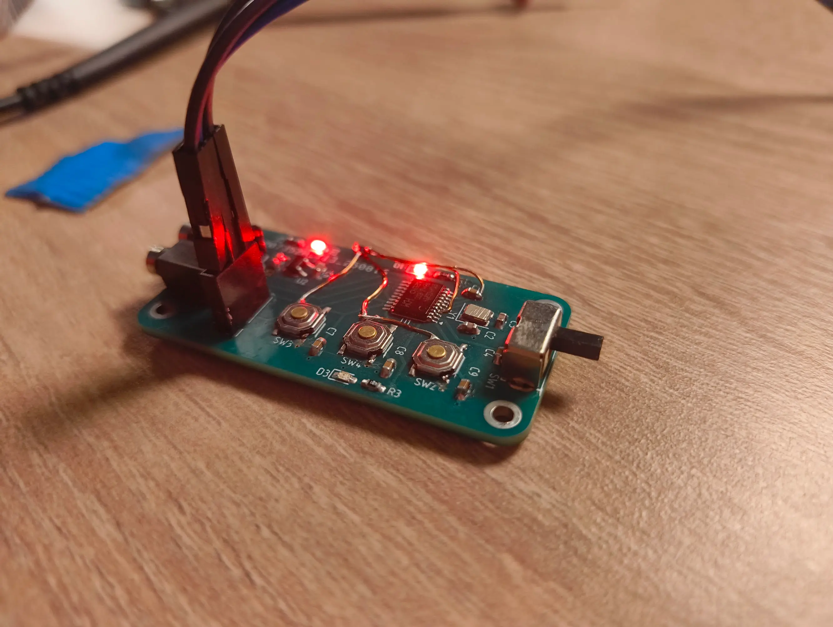
This is what the final PCB in its bodged bodged form looks like. Not the prettiest but working reliably. The only real problem now is that none of the 2.5mm audio jack thingies work because I ordered ones that don’t expose all three pins so there’ll have to be a second run.

Hardware
This PCB is still not really operator friendly so I needed a housing. I designed a clamp that clamps onto the 15mm rod often used when rigging cameras and a two part design holding the pcb and adding surfaces to click the buttons.
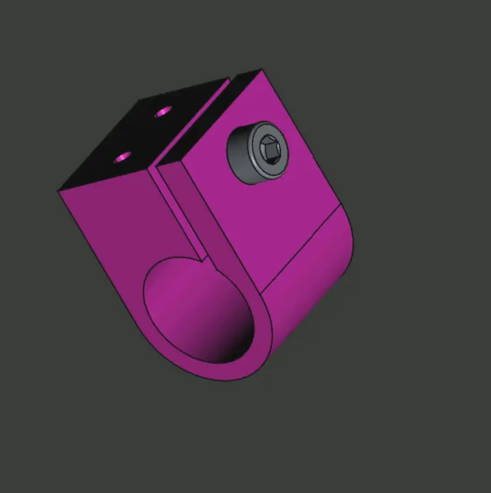
I designed it be kind of easy to make from aluminiuum using hand tools (hacksaw, drills, taps, reamer) but the 3d printed version I made for prototyping is proving to be more than strong enough.
Appendix
Links
Table: Button IDs
| ID | Button |
|---|---|
0x48 |
User Button 4 |
TODO: If I every have the interest in reversing other buttons I will add them here.